1.2: Computer Systems: Hardware and Software
1.2. Systems and Models
Throughout this volume, we are considering the idea of computer systems from a perspective that strives to apply insights from systems theory. From this view, a organisation is an integrated collection of entities and their interactions. The computer itself is a system. Computers are assembled from disparate hardware components that include a central processing unit of measurement (CPU), storage devices, input and output devices, random admission retentiveness (RAM) cards, and a printed excursion board (PCB) that links them all together. A software Os executes on meridian of these components, thus integrating their independent functionality into a more than complex entity. To fully understand the nature of the computer as a whole, it's important to empathize the components' independent functionality as well every bit how they piece of work together.
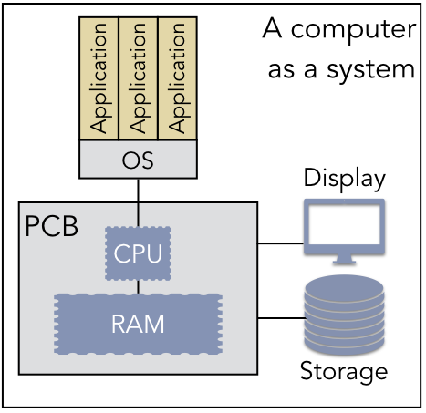
Figure 1.two.1: A estimator is a organization of interacting hardware and software entities
The system is made more complex by adding application software to the mix. Each application is constructed from code modules, variables, and other run-time retentiveness structures that are compiled and integrated to provide a single higher-level role. Only software does not run itself; the software must be executed within the greater context of computing, as a sequence of steps performed by a physical computer with the help of an OS. Some applications run in isolation from one another, but they even so require the Os and hardware. Others communicate with services that provide information or perform complimentary tasks, allowing the developer to build more powerful software without having to offset from scratch. Figure 1.2.1 summarizes this view of the computer as a organization of interacting components.
In short, all of computing is a system. As reckoner scientists continue to explore the power of computing, we can have this claim fifty-fifty farther to advise that computing is made upwardly of a system of systems. In order to stream a moving picture over the Internet, the application software must integrate network connectivity and local file storage, probably with the aid of a graphics processing unit of measurement (GPU) that improves the visual quality of the experience. Each of these hardware and software components are systems, and the application is coordinating their interaction to serve the user. As another example, consider large-calibration scientific projects that model changes in the climate or advanced quantum mechanics phenomena. This type of work involves linking thousands of parallel calculating nodes that coordinate their calculations and exchange data every bit needed, creating truly complicated systems and interactions. Our goal is to empathize the mutual principles and strategies that make these systems work.
ane.2.1. Models equally Representations
A start step toward understanding a system is constructing a model – a simplified representation – of the system. Figure ane.2.1 above is a model of a figurer as a system. Equally a simplification, models necessarily omit details that are nowadays in the organisation itself. Some models have visual representations, facilitating human interpretation of the arrangement. That is, visual models are very proficient tools for people to make sense of the entities and their interactions. System designers, developers, and users can utilise visual models to avert mistakes. Other models are formal, written in a mathematical specification language. One way to characterize the differences between models is to describe their level of abstraction. Visual models may accept a relatively low level of brainchild, including details that are aesthetically pleasing but not of import. Formal models have a relatively high level of brainchild, omitting everything except the blank minimum.
Consider the models shown in Figure ane.ii.2. The model on the left has the lowest level of abstraction, as it includes details that show a yellowish box on a greyness ramp. This scenario is then converted into a free-torso diagram in the middle. Gratis-body diagrams are used in physics to illustrate the forces interim on an object, while removing unneeded details such equally the cartoon of the box and the ramp. The equation on the right is the formal model that captures this data. The net force F is the sum of the forces created by gravity (mg), the normal forcefulness N, and the force of friction \(F_f\). All iii models convey the same information, but they provide different levels of abstraction.
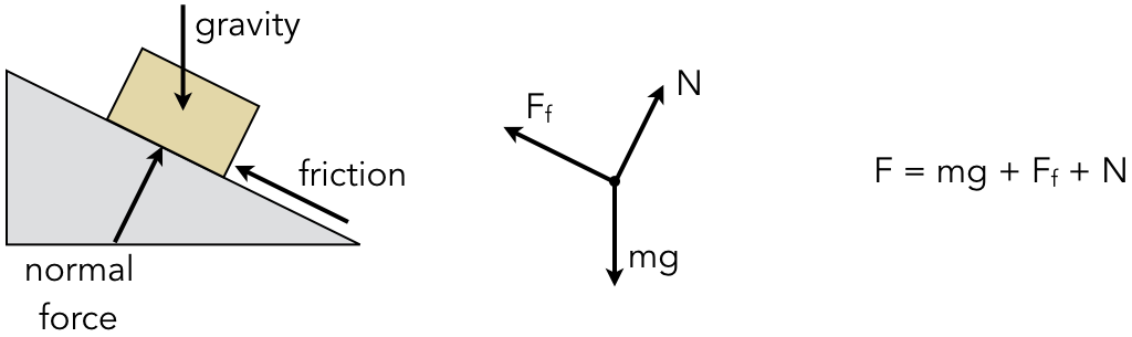
Figure 1.2.2: 3 models for the aforementioned physical miracle
A static (or structural) model describes the fixed, unchanging features of a arrangement, while omitting explanations of how the system or entities change. Readers with a groundwork in object-oriented programming may be familiar with class diagrams created using unified modeling language (UML). These models describe features like grade inheritance and sub-typing, while omitting characteristics like the values of an object's variables or the messages it uses to communicate with other objects. Throughout this text, we will focus repeatedly on i particular type of static model, the organization architecture.
In dissimilarity, a dynamic (or behavioral) model focuses on changes to the organisation. These models are peculiarly important to agreement systems, considering many of their key features are emergent properties. An emergent property is 1 that results from the dynamic features of the system and is not intuitive from static models alone. Nosotros will exist using two dynamic UML models throughout this book. A state model describes the system'southward possible states – divers past meaningful combinations of arrangement parameters – and the possible transitions between them. For instance, a streaming video service may characterize different states to represent "requesting the video," "buffering received data," "pausing the video," and "playing the video." A sequence model illustrates the order of messages and central events that a organization experiences over fourth dimension. 1 use of a sequence model is to describe a specific guild in which state transitions occur. These models provide a clear illustration of network communication protocols and messages to coordinate parallel and distributed ciphering.
ane.2.2. From Models to Implementations
Models are useful tools for analyzing and illustrating the beliefs of a system. Well-constructed models of the natural world can help scientists develop insight into and explain real-earth phenomena, such as the chemical reactions that release free energy stored in food, the moving ridge-like behavior of electrons in an atom, or the fractal designs in crystals. User manuals for appliances, vehicles, children's toys, etc., use illustrations as models to convey information to consumers who are not necessarily experts in the field.
In dissimilarity to many other fields, the field of computer systems places a stiff emphasis on turning models into implementations. That is, our goal is not simply to build and translate models, simply to turn these models into working artifacts. This implementation process tin can exist quite challenging and creates many opportunities for errors; mistakes that crusade the organization to behave differently from the model can return the model useless or, even worse, increment confusion. Every bit such, much of our focus throughout this volume is on successfully turning models into concrete, executable implementations.
0 Response to "1.2: Computer Systems: Hardware and Software"
Post a Comment